 An excellent article in IEEE Spectrum magazine gives a rundown of the origin of the Arduino board, outlining the motivations behind the open source design and the increasing impact it has on creative communities all over the world. It's a good read for answering the question, "What is Arduino?"
Monday, November 7, 2011
IEEE Spectrum: The Making of Arduino
An excellent article in IEEE Spectrum magazine gives a rundown of the origin of the Arduino board, outlining the motivations behind the open source design and the increasing impact it has on creative communities all over the world. It's a good read for answering the question, "What is Arduino?"
Thursday, November 3, 2011
Flight Suit Excursions, Grinder Timer V4
 I've had a lot of fun with my Arduino-based projects lately! I got the flight suit working again for Decompression last month and had a blast dancing and hanging out in the crushing crowds.
 I wore it again last Saturday night for the work Halloween party and then again Monday night for 7 Walkers at the Great American Music Hall where Liz balanced out my high tech audio meter with her low tech VU meter-- analog and fully manual :)
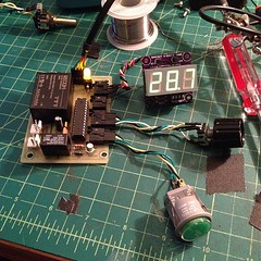 Next up is V4 of the coffee grinder timer, a one-off to replace the V2 timer we're using now. It's an all-in-one circuit board designed to fit in a Hammond 1455-series case. There's an AC-DC converter on the board to supply 5V, and breakouts on the left (in white) for power and on the right (black) for the display, light sensor, rotary encoder, and lit button. I may finish it without the light sensor since it's so close to being done and looks so much better (especially on the inside!) than what we're running now.
Sunday, September 11, 2011
Suit Success, Refurbishment...
Three nights out on the playa, the light suit did not disappoint! So much fun to embody the bouncing red LED, for me and folks around me. It ran so much the second night-- music response mode and a high brightness can really draw current-- that I went through both batteries, ending the night unlit! The third night with all batteries charged and on-hand, there was no shortage of power and I ran it bright, but it was getting rough after so many miles, with a few segments not responding and a few dead 3-LED groups. All the time, the system worked beautifully, and I left it running when I finally took it off and stuffed it in a box Sunday morning, rippling and flickering, so bright before switching off.
Taking it out of the box Thursday in a puff of dust, a few segments did not respond but the system worked just as when I put away. I stripped out the main left arm board, all board-to-board cabling, the MOSFET boards, and then the light strips, pulling them off one at a time, removing the right arm accelerometer last. The suit and (surprisingly) sneakers made it through the wash and look great. I'm checking LED strips now, making a to-do list of fixes, remakes, and changes. I'll clean off all the boards and hook it together for a full pre-test, and then stuff it back in the suit.
Taking it out of the box Thursday in a puff of dust, a few segments did not respond but the system worked just as when I put away. I stripped out the main left arm board, all board-to-board cabling, the MOSFET boards, and then the light strips, pulling them off one at a time, removing the right arm accelerometer last. The suit and (surprisingly) sneakers made it through the wash and look great. I'm checking LED strips now, making a to-do list of fixes, remakes, and changes. I'll clean off all the boards and hook it together for a full pre-test, and then stuff it back in the suit.
Tuesday, August 30, 2011
Flight Suit Works!
So much to do before we take off for BRC but the suit is fully functional!
I'll post photos and videos and all design filesafter the long weekend at some point, but here's a video showing the audio mode, which was the target all along:
Polishing work to deal with:
I'll post photos and videos and all design files
Polishing work to deal with:
- Test foot "A" and "B" strips Velcroed to shoes; hook and loop glue should be cured by tonight.
- Finish remote control: straighten display, sand outside, glue top layers.
- Tidy up buttonhole wiring and shift bands to correct alignment along Velcro loop bands.
- Finalize light strip lengths: clip any extra length and seal ends.
- Come up with a better remote control attachment... clip? hook? Velcro?
- Make a cover for the ZX-Sound audio input board.
Wednesday, August 24, 2011
(F)Light Suit Progress: Almost There!
So much progress in the last two weeks, the big milestones being...
- I got the MOSFET boards and built three-- they worked right away! As expected I needed resistors between the 595 outputs and the MOSFETs; didn't notice that until I hooked up the third one and things weren't behaving. I'm not crazy about the screw terminals but they'll be OK.
- Testing the MOSFET outputs with all 22 segments-- 53' of light, so bright! The first tests were just "All Fade" mode.
- Expanding the program to sense arm angles. The routine automatically sets arm levels, either up/down or matching angle, and how many levels there are (since arms up can create a new level).
- Adding a proper "Rolling" mode to sweep a band or bands over the whole suit, top to bottom, with variables delay (ms), brightness, direction, and number of bands (density). Seeing all the bands rolling through was a relief.
- Sewing is awesome. I've sewn 10 out of 19 "loop" side Velcro bands into the suit: both legs and the hips and waist.
- ZX-Sound works! Filtering and sampling will be the last things I dial in, but I have working bouncy light code, smoothed and at whatever Hz I want, dynamically computing the high and low so it will bounce if it's quiet or loud.
- Integrate audio sketch into main line, finish filtering code, and use filtering code for gravity sketch,
- Finish sewing hook-side Velcro strips onto the suit,
- Cut the loop-side Velcro for the light strips and stick it on with silicone,
- Measure and cut and route in-suit leads: 4 solder points each, 6 pieces of shrink,
- Sew in conduit for left-to-right board, battery, audio, and accelerometer leads.
- Address shoes, hat(s), headband mounting and routing...
Thursday, August 11, 2011
Nanode: Arduino-compatible with Ethernet
 The Nanode project from (the?) London Hackspace has been on my radar but didn't make the spreadsheet since I was waiting for it to become available. Well, it's out ($40 kit), and it seems to be a hit!
Unlike the Arduino Ethernet and shield and other boards with built-in ethernet, the Nanode does not use the Wiznet W5100, instead using the Microchip ENC28J60 found in JeeLabs EtherCard, and you can even program it over ethernet!
Not all rotary encoders are created equal...
 I had a hell of a time getting the (F)Light Suit remote control to work with the Modern Device LCD117 backpack and inexpensive BI EN11-HSM1AF15 rotary encoders. It turned out that I was having two issues:
- The LCD117 was getting its updating commands too quickly, so chose to reset instead of display, and
- the rotary encoders make contact so quickly when stepping up or down, my debounced code for bigger rotary encoders with more even click timing wasn't working.
Wednesday, August 10, 2011
(F)Light Suit Major Components
The main components of the (F)Light suit:
(Updated 8/15/11)
(Updated 8/15/11)
| Component(s) | Source | Status |
| LED strips | DealExtreme | 22 strips with connectors, need sealing and velcro backing. |
| 8-channel MOSFET Output Boards | DorkbotPDX board order | Three built and tested, work perfectly |
| Arm accelerometers | Modern Device | Left one on main board, right attached with 3-wire lead across shoulders |
| Black flight suit | Amazon | Needs velcro for LED strips |
| Arduino-compatible main board: Minimalduino 105 | DorkbotPDX board order | |
| Arduino interface board: Adafruit protoshield | Adafruit Industries | Done, ready for mounting and cable threading. Ports for MOSFET output boards, right accelerometer, remote control, audio sensor |
| Remote control | homemade, various parts | Needs laser-cut acrylic surround, rot 2 flaky |
| Batteries | eBay | 12V, 4800mAh Li-ion battery packs with barrel connectors, powering third MOSFET board. |
| Audio input: ZX-Sound board | RobotShop.com | Test, add light, change connector, paint, velcro back |
| Missing anything? | ||
Wednesday, July 27, 2011
Ethernet Arduinos (and Compatibles)
 Also on the spreadsheet, three boards with built-in ethernet:
- There's finally an official Arduino Ethernet ($60), complete with RJ45 port. It has an FTDI cable header for programming (no USB), a microSD card slot for storage, and there's an optional PoE daughter card.
- SparkFun also released an Arduino-compatible board with ethernet, the Ethernet Pro ($55), but without the SD card slot. It's less cluttered than the official board, hopefully the price will come down as more people build projects around them.
- Additionally, the Freetronics EtherTen ($70) includes a microSD slot and (mini) USB interface.
Call me cheap, but these all seem overpriced, being based around a $4 microcontroller! With a basic Arduino board at $20 and WIZ811MJ module at $20, why isn't the SparkFun Ethernet Pro $40 or $45?
Tuesday, July 26, 2011
More 'duinos on the Spreadsheet
I've continued to add Arduino-compatible boards to the spreadsheet, bringing the count to 119 boards. You can get there easily by remembering "allarduinos" and going to http://tinyurl.com/allarduinos or http://bit.ly/allarduinos.
Some recent additions to the spreadsheet:
Some recent additions to the spreadsheet:
- Three (!) clock boards from Wise Time With Arduino:
- Wise Clock 3 with a 32x16 Red-Green LED display (from Sure Electronics) has many different modes, including Pac Man, game of life, Pong, and... make your own!
- ClockTHREE Junior (aka C3Jr), a collaboration with WyoLum, which is similar to the QlockTWO readable clock.
- DWex, "Duino Watch for experimenters"-- chock full of SMD LED goodness; this actually came out last year but I missed it.
- Wise Clock 3 with a 32x16 Red-Green LED display (from Sure Electronics) has many different modes, including Pac Man, game of life, Pong, and... make your own!
 From SparkFun comes the PTH (plated through-hole) Kit, very similar to Diavolino and my Minimalduino, but surprisingly priced at $30. It doesn't seem up to SparkFun's high standards though, since there is no power switch and the electrolytic capacitors are too tall, so shields won't fit.
Monday, July 25, 2011
(F)Light Suit Progress: PWM!
I had a frustrating time trying to get a PCA9685 working-- it wouldn't even reply with its register byte values. I've interfaced with other I2C chips and didn't expect problems, but trouble was all I got.
Poking around the Arduino Forum trying to find any examples with a PCA9685, I found the thread on Elco Jacobs' new ShiftPWM library to drive the outputs of the ubiquitous 74HC595 shift register with 8-bit PWM precision. His demo video is on the right. The example sketch was so straightforward, I had two chips driving-- and dimming-- 16 red LED's in minutes.
 Once I saw those red LED's cycling, I considered that part of the project done-- thank you, Elco!-- and started laying out a driver board with a 74HC595, eight outputs hooked up to MOSFETs and test LED's, and screw terminals so they can be daisy chained. With the DorkbotPDX order deadline this morning, I had to stay up late laying it out and getting a final Eagle brd file ready, and hopefully it will work; I wasn't that excited about asking for six copies of a 3.9"x2.1" V001 design and having no time for a second run if they don't work, but... hey, they'll work!
Here's the Eagle schematic: pdf, sch. And the board: pdf, brd.
Sunday, July 17, 2011
LED (F)Light Suit: Ramping Up
 I've been mesmerized by bouncing red LED's since the early '80s. LED's were mostly red, needle-style VU meters were on the outs, we hadn't yet graduated to green-yellow-red meters, and I grew a special place in my heart for those bouncing red lights. We also had KITT and the Cylons: bouncing red lights were and still are awesome ("rad" had not been invented yet).
I put together a black flight suit with red EL-wire segments for Burning Man in 2008 but did not have time to build the sequencer and control system I envisioned, so it was an on/off affair, or it pulsated to the music before the small batteries died.
Working on a suit for this year's burn, I've decided to return to the original concept-- red LED's-- and am working on the major areas now:
- Suit electronics: Arduino core, I2C port expander w/PWM output using PCA9685 16-channel, 12-bit PWM I2C-bus LED controller driving power MOSFETs, one per segment. There are 17 segments in my design, so I'll use the port expander and then another spare pin to trigger the 17th channel.
- Audio metering: I have a MaceTech Shifty VU shield working but I wonder about adjusting levels on the fly, and how to best get a mic input to it or something similar. There will be other modes for sequencing the lights, but bouncing VU meter is the primary mode I'm looking for.
- Segment planning: location and length of each segment, power lead routing, attachment to suit. This is going well, with the first seven (of 22) segments cut and tested last night from my first 5M strip from DealExtreme; the suit will need 53' of light strip so I've ordered more.
- Power: rechargable 12V power packs are easy to get; not sure how to recharge them on the Playa.
- Remote control: would like to have a small, wireless remote to control modes and mode parameters.
- The program: I have a list of modes I'd like to switch between, some of which have parameters I'll want to adjust on the fly. Ideally I'll be able to edit the program during the day if I come up with new ideas while I'm in BRC.
Saturday, July 16, 2011
What is "Minimalduino"?
I started working on the "minimalduino" design as...
- a minimal hardware design for an Arduino-compatible board. At heart, it is very similar to the Dorkboard, but
- designed to match the form factor of the "official" Arduino boards so users can benefit from the many, many shield boards designed to fit on top. While (awesome) boards like EMSL's Diavolino are also low-cost and shield-friendly, I wanted to explore
- optional hardware configurations, with different power connector options (pin headers, JST connector, barrel jack, screw terminals, or mini USB jack), 5V and 3.3V power regulation and optional voltage switching and regulator bypassing, and options for crystal and caps or a resonator. I also wanted to have
- better shield-friendliness by placing LEDs (power and D13) and the reset switch (side switch or top switch) at the edges of the board, and lastly, I wanted the board to be
- single-sided, home-etchable with wide traces and minimal jumper wires. There is still work to be done to reduce jumpers, but it improves on the the S3V3 "Severino" board which doesn't match up size-wise (it's bigger), the standoff mounts don't match, and it uses a DB9 serial connector instead of the now widespread FTDI USB-serial breakout cable.
Thursday, June 16, 2011
3-Digit 7-Segment Display With an SAA1064
Working on the grinder timer project, I built out a basic circuit (EAGLE .sch) with an NXP SAA1064 and resurrected a test sketch (Arduino .pde) for it. The SAA1064 works beautifully for driving common anode 4-digit 7-segment displays with constant current per segment, from 3 to 21 mA in 3mA increments; in this case I'm only driving three digits since that's what the design calls for.
There are two buttons in the test sketch (on D10 and D11), the first to change count modes (seconds, tenths, hundredths, hex, and "chase") and the second to cycle through the seven current settings.
This schematic is identical to one I did a board layout for with an SO24 package chip, but for some reason those boards didn't work; maybe something in manufacture or assembly bridged pins somewhere. I'll redo the layout and see what happens, with vias further from pads.
Wednesday, June 15, 2011
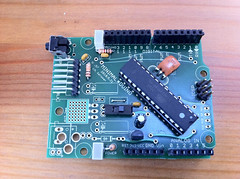
Minimalduino 105: Nice!
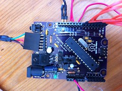 I built out one of the "V.105" boards I got a few weeks ago from the DorkbotPDX PCB order, and it works beautifully, almost identical to the version 107 I posted files of, with "5V/3.3V" voltage and "FTDI/IN" power selector switches. I mounted a mini USB socket and a 7805 regulator, in addition to the barrel jack for power in.
I've gone to whole number versioning btw, no need for "always under 1" versioning or major/minor versions, and if I need to go higher than 999 (huh?!), I can just use four digits.
Top and bottom labeling came out great, including the Open Hardware logo, though the letters mush together a little. Also, the "FTDI" header label didn't print at all, maybe there's a problem having two "FTDI" text labels.
One issue is that the drills for the main female headers are smaller than those on versions 89 and 97 boards, even though they use the same parts in EAGLE! I'll check the parts and maybe swap them out. That's a bummer-- I had to drill them all out to mount the headers, which ripped some of the pads off the fiberglass, but thankfully they stayed connected to the traces.
Minor edits for the next version:
- Move the power input components to give electrolytic capacitors more room to accomodate shorter/fatter ones or taller ones mounted horizontally. As it is, the 100uF cap at the input is jammed between the .1uF cap and the barrel jack. [done]
- Rotate LED's so they can be mounted horizontally for better side viewing when using a shield. [done]
- Add heat sink polygon and vias under the 7805 tab.
- Fix the Sparkfun mini USB through-hole part: its outline is on the bPlace layer, not tPlace where it belongs. Or just use a different part. [done]
- Check female header drill diameters.
- Add 2-pin header at the reset button to make it easier to add a remote panel-mounted reset button. [done]
- Round the corners; looks nice on the Freetronics boards. Also check Uno outline and drills to make sure things are lined up right. [done]
Monday, May 16, 2011
MinimalDuino 107 Pattern
 After submitting the 105c version to the DorkbotPDX PCB order, I mentioned I'd make one at home, but the traces looked so thin on paper and I didn't like the routing of gnd to the crystal area, so I made a few changes to optimize it for toner transfer and home etching.
Here's a shared folder with the updated, v107 EAGLE files and a 600dpi jpeg for toner transfer. See the low res at right, or click for higher res; get the full res jpeg here.
Monday, May 9, 2011
Minimalduino v.105: Curvy Trace Fun
I've been trying out some Hope RFM12B radio modules-- very cool and inexpensive!-- which run off 3.3V. I've been using MinimalDuinos since they're 5V/3.3V switchable, and I got three version .97 boards made last year, with curvy traces, and they're coming in handy.
I have a few boards I'll need to get made over the next few months, so to warm back up with EAGLE, I polished up a straight (normal) trace version .105 board and set to curving it up. It took about an hour and a half, going around trace by trace in move mode, lots of command-clicking and dragging in the middle of trace segments to adjust their arcs. I submitted it to the DorkbotPDX PCB order before the deadline hit, and I can't wait to see what I get :) Design files and snapshots can be found here.
A key goal of the design is to have a good single-sided pattern for home etching, so I'll also make one by hand after fattening up as many traces as possible.
V.105 with straight traces:

Compare to V.105C, with curvy traces:

I have a few boards I'll need to get made over the next few months, so to warm back up with EAGLE, I polished up a straight (normal) trace version .105 board and set to curving it up. It took about an hour and a half, going around trace by trace in move mode, lots of command-clicking and dragging in the middle of trace segments to adjust their arcs. I submitted it to the DorkbotPDX PCB order before the deadline hit, and I can't wait to see what I get :) Design files and snapshots can be found here.
A key goal of the design is to have a good single-sided pattern for home etching, so I'll also make one by hand after fattening up as many traces as possible.
V.105 with straight traces:
Compare to V.105C, with curvy traces:
Friday, February 25, 2011
Spreadsheet: "Date Added" Column, More Boards
So many people have asked for a column on the Arduino-compatible board spreadsheet showing the date when each board was added, so I put that on the spreadsheet this week. I had to sift through the revisions, but it wasn't too much of a pain.
Also new to the spreadsheet:
Also new to the spreadsheet:
 Six boards by the Indian company Bhasha, all through-hole except for the FTDI USB chips, mostly simple designs but it's clear from the traces that the boards were reworked slightly. Interesting to see the "Severino" Single Sided Serial V3 design offered for sale, something I haven't seen elsewhere.
- Zigduino by Logos Electromechanical is offering their first run of IEEE 802.15.4 radio-equipped boards for $70. I've been looking forward to these boards coming out, but the price seems high given that you could buy an Arduino FIO for $25 and an XBee module for $19, so $44 total, or a Freakduino Chibi for $33. I hope the high price is only for this first run and that it is lower when Logos goes into full scale production, but I also wonder if it's as easy to use as the widely available XBee modules for which there are many example sketches available. It does have XBee "Pro" capabilities though, and I'm not familiar enough with 802.15.4 to really compare it to other offerings. I look forward to more complete documentation on its specs along with full design files since it's unclear what its equipment and capabilities are.
Open Source Hardware Definition 1.0
The Open Source Hardware ("OSHW") definition version 1.0 was released a few weeks ago, and a bunch of organizations and people (like me!) have signed on in support of the definition and of OSHW in general.
One of my favorite parts, emphasis mine:
One of my favorite parts, emphasis mine:
4. Derived WorksIf I'm reading that right, by allowing and not obliging derivative works to adhere to the definition, industry is encouraged to incorporate as much or as little OSHW thinking as they like into their products. I think this is key for encouraging manufacturers at large to think in terms of making their products hackable, but more importantly, servicable. Of course companies will need to lay out all kinds of disclaimers for when you break their products when you were trying to fix them, but that's already standard practice. This is getting interestinger all the time...
The license shall allow modifications and derived works, and shall allow them to be distributed under the same terms as the license of the original work. The license shall allow for the manufacture, sale, distribution, and use of products created from the design files, the design files themselves, and derivatives thereof.
Monday, February 14, 2011
Spreadsheet Edits
I've made some changes to my Arduino-compatible boards spreadsheet lately: I added a few boards, removed boards which are no longer available, and made some general changes.
Added:
Removed:
Added:
 |
|

|
|

|
|
- A bunch of boards by Fundamental Logic which apparently stopped accepting orders in May of 2010. That makes me sad since they offered some interesting boards, but thankfully the designs are still online for reference. My favorites: iDuino, StickDuino, MPGuino.
- Modified Pico was a very compact, breadboard-friendly Duemilanove-compatible board. Thankfully details (including design files) are still available.
- Rampage Robot Base V4 was an Arduino-powered robot platform with headers for a shield. Looks like its creator has moved on to more complex microcontrollers.
- Zuccherino by Evil Mad Scientist Laboratories was to be "a low-cost, scalable, and extremely versatile open-source motion control platform," but the project has not had an update in a while. I look forward to more from this project.
- "Flexi" was an inexpensive breadboard-friendly clone, not sure what happened but the domain now hosts a useless/spammy link page.
- I just added a "By" column for designer, author or manufacturer. I'd like it to be simply "Author," but some companies [cough] mostly sell other peoples' designs, so I'm not sure whom to credit.
- I'd like to add more information about when boards were edited or checked, but wading through the revision history in Google Docs is a pain. A few people have suggested this and I like the idea, but I can't figure out how to track down the details.
- I updated a bunch of boards' links, prices, and chip; a few use ATmega328s but used to be ATmega168s.
Wednesday, February 9, 2011
Minimal*duino V.96
 I've done a little work on my "Minimalduino" Arduino-compatible board design lately:
- Moved the fourth standoff mount hole to line up with the Uno's new fourth standoff hole (which they didn't make aligned to the one across the way!).
- Fattened up the traces to make it more home-etcher-friendly: .016" and .024" traces, .018" min. separation.
- Spread out the components, reduced the jumper count, and removed the I2C header.
- Added pads for a mini USB jack, for power only. (I'm not sure about the grounded heat sink of a 7805 shorting to the 5V trace so I put in a solder bridge, but it's fine for making at home using real wires for the top layer jumpers.) So many options for powering this sucker!
Thinking about running this at 3.3V, I don't think it would work right for programming or for running with the FTDI cable attached.
 Update: I had some v.97 boards made (DorkbotPDX order ftw!), same as .96 but with curvy traces and a few parts moved a little, here's one assembled:
Wednesday, January 5, 2011
Arduino: What Direction?
In spite of the year-end hype surrounding the Arduino Uno, and while I like seeing Arduino hit its 1.0 release, other Arduino-compatible boards get me more excited. If Arduino is a low hurdle access architecture for the ATmega**8 line of microcontrollers, I'd prefer the extra circuitry to be optional:
Here are a few boards comparably-priced to the Uno that may be more useful for real applications since they have the Arduino core but different circuits for power, communication, or extra capabilities:
- Power regulation: why embed regulation in each board when it's not always needed? And what about regulation or step-up converters for battery-powered projects?
- Board voltage: There are good reasons to use 3.3V or 5V depending on applications, why are so few boards switchable?
- Programming interface: While USB (and its decoder chips) is ubiquitous, so (still) are serial and ethernet, and (increasingly) XBee. Why not make the programming/serial interface optional or external?
- Real estate: There is only so much room in the standard Arduino form factor. Why not use that space for useful circuitry that would be tricky to locate externally?
Here are a few boards comparably-priced to the Uno that may be more useful for real applications since they have the Arduino core but different circuits for power, communication, or extra capabilities:
- Wiseduino ($34 kit) has a DS1307 real time clock with backup battery, a 256Kbit EEPROM chip, header pins for the Adafruit XBee adapter, and 6-pin FTDI cable interface.
- Freakduino Chibi ($33 kit) has built-in 802.15.4 (XBee) radio and optional ($3!) battery voltage regulation so you can input from .7V to 6V.
- Arduino FIO ($25) has a MAX1555 LiPo charger, power regulation, and an XBee socket.
Subscribe to:
Posts (Atom)
